

CALDER NORTHERN GROUP
X-tra TRAIN ORDERS June 2019
Start-up instructions when operating North Western Mills layout.
Hi there,
Alan Wyatt has kindly set out a start-up procedure when switching on the North Western Mills HO scale layout in the clubroom. These instructions are for members to follow in sequence to ensure the layout powers up correctly and in the right order.
When you are scheduled to operate at weekends according to the rota then these instructions should be followed to make sure no hiccups occur and you can have a trouble-free session.
A copy of these instructions will also be placed on the clubroom notice board.
Terry Wynne
Secretary
CREWE DIGITRAX START-UP & SHUT DOWN
START UP
| Number | ITEM | Check |
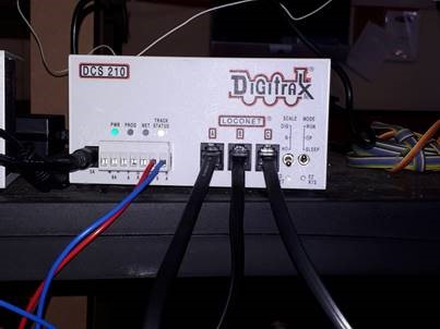
| 1 | Check position of switches on the DCS210 Command Station, the mode switch should be set to RUN, and the scale switch should be set to HO.
|
|
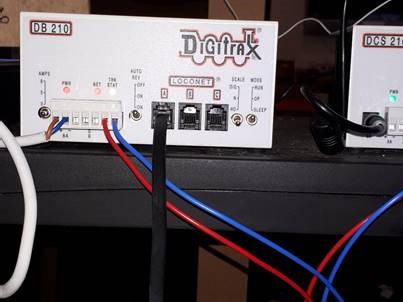
| 2 | Check position of switches on the DB210 Booster, the mode switch should be set to RUN, the scale switch should be set to HO, the AUTO REV switch should be set to OFF and the AMPS switch should be set to 5.
|
|
| 3 | Turn the power for the layout on at the wall. Switch on the Digitrax equipment by switching on the things plugged into the 6 way extension one at a time.
Start with switch 1 the Loconet power supply, switch it on. The UR92 on top of the pole should show a steady red light and a blinking green light.
Using switch 2 switch on the Booster, the lights on the DB210 should show-
Using switch 3 switch on the Command Station, the lights on the DCS210 should show-
The red light should have gone out on the UR92 to be replaced by a blinking green light showing that the wireless transmitter is talking to the control station.
The circuit breakers should all show a steady red light on each breaker. If they don’t and the track indicator lights are off on the Command Station and the Booster then find a DT500 controller, put a charged battery into it and then plug it into the layout. Press the PWR switch to turn on the controller and see the following screen display.
Press the Y/+ key for a couple of seconds. The lights on the breakers and the track status lights on the Command Station and the Booster should illuminate to show that the track power is on.
Switch 4 controls the power to the points system.
Switch 5 is for the battery charger.
Switch 6 is for Mikes’ layout For normal operation check,–
See also the pictures below,
|
|
| 4 | Select the controllers you want to use and using a batteries from the fully charged section of the battery tub fit batteries into the controllers.
Then, if it is a wireless throttle, plug it into the layout to enable it to join the duplex group ready for wireless operation. After about 10 seconds unplug it from the layout. |
|
| 5 | At this point if the breakers are all showing a red light there should be power to the tracks, so put a loco on the layout, select it and see if it responds to the controller. If it doesn’t plug the controller into the layout, reselect the loco and see if it responds to the controller. If it now responds unplug the controller and check that the train can now be controlled wirelessly.
|
|
| 6 | If a UT4D controller does not appear to be working properly then plug it into the layout, if it now works correctly then unplug it and change the battery for a fully charged one.
|
|
| 7 | A DT500D must have a 9-volt battery installed for tetherless operations. When you install the battery press and hold the PWR key to turn your throttle on, the throttle will report the battery voltage then display the last screen displayed before the throttle was powered off. If the voltage shown is less than 6.5Volts then the battery must be changed or the controller plugged into the layout. NB this will not charge a flat battery.
|
CHARGING BATTERIES
| Number | ITEM | Check |
| 1 | Plug a battery into any of the 10 bays in the charger unit. A red light alongside the battery slot shows that the battery is charging. When the red light turns green then the battery is fully charged and can be removed and placed in the tub for charged batteries.
Charging batteries will take up to 4 hours for a totally flat battery.
|
SHUT DOWN
| Number | ITEM | Check |
| 1 | At the end of a session despatch any locos from the controllers to avoid problems on start up at the next session, see controller manual for how to do this. Turn off the power to the layout by turning off the switches on the extension lead and then turn of power at the wall.
|
|
| 2 | Remove the batteries from the controllers, they should then be put in the “used” part of the battery container and every Wednesday used batteries should be charged and put into the charged section of the battery box. This should ensure sufficient charged batteries to begin a weekend running session.
|
CREWE DIGITRAX START V4
Leave a Reply